
Choosing the right pneumatic cylinder requires more than matching a cylinder to the weight of a workpiece. Engineers must consider the required force, stroke length, operating pressure, movement speed, installation space, and working environment. An undersized cylinder may fail to complete its task, while an oversized one can increase compressed air consumption and equipment costs.
For industrial automation production lines, the best approach is to define the working conditions first, calculate the required force, and then verify the cylinder type, stroke, speed, and mounting arrangement. This guide explains how to make these decisions step by step.
A pneumatic cylinder converts compressed air energy into linear mechanical motion. It commonly performs pushing, pulling, clamping, lifting, and positioning operations.
For example, a cylinder on an assembly line may push a component into a fixture before another machine completes the assembly process.
Before selecting a cylinder, identify three factors:
These details determine which cylinder type and size should be considered.
Different cylinder designs suit different applications.
| Cylinder type | Typical application | Main consideration |
| Standard cylinder | General pushing and pulling | Check force, stroke, and mounting |
| Compact cylinder | Limited installation space | Check available stroke and dimensions |
| Miniature cylinder | Small mechanisms | Verify force and connection size |
| Guided cylinder | Movement requiring additional guidance | Check allowable loads and moments |
| Rodless cylinder | Long stroke linear movement | Check load support and guidance |
| Clamping cylinder | Holding workpieces in fixtures | Check clamping force and mechanism geometry |
A standard cylinder may be sufficient for pushing a carton. However, if a component must move accurately while resisting lateral forces, a guided cylinder or separate linear guide may be more suitable.
Cylinder type should be selected according to the mechanical task, not appearance or price alone.
It is also important to distinguish between single acting and double acting cylinders. A single-acting cylinder typically uses compressed air to drive movement in one direction and a spring or external force to return. A double acting cylinder uses compressed air alternately on both sides of the piston, allowing controlled extension and retraction.
Double acting cylinders are common in automation applications requiring active control in both directions.
The bore diameter affects the cylinder's theoretical output force.
F = P × A
A = π × D² / 4
Where F is force in newtons (N), P is pressure in N/mm², A is piston area in mm², and D is bore diameter in millimeters.
Suppose an assembly station requires 800 N of axial pushing force, and the pressure available at the cylinder is 0.6 MPa.
For a 50 mm bore:
A = π × 50² / 4 ≈ 1,963.5 mm²
The theoretical extension force is:
F = 0.6 × 1,963.5 ≈ 1,178 N
If an illustrative 80% allowance is used for preliminary screening, the estimated usable force is approximately 942 N. This exceeds the 800 N requirement, making a 50 mm bore a potential candidate.
However, 80% is not a universal efficiency rating. Actual selection must account for seal friction, pressure losses, dynamic loads, and manufacturer performance data.
For a single rod, double acting cylinder, retraction force is lower because the piston rod reduces the effective working area. Both directions must be checked if the application requires significant force during extension and retraction.
The following table shows theoretical extension forces at 0.6 MPa. Actual usable forces will be lower.
| Bore diameter | Theoretical extension force |
| 32 mm | 483 N |
| 40 mm | 754 N |
| 50 mm | 1,178 N |
| 63 mm | 1,870 N |
For an 800 N requirement, a 40 mm bore would not provide sufficient theoretical extension force at this pressure. A 50 mm bore is a more reasonable candidate for further verification.
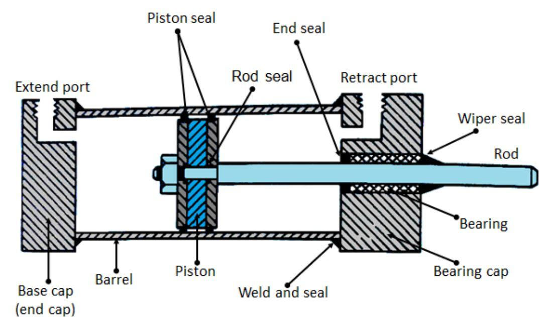
Stroke length is the distance the piston travels between its retracted and extended positions.
If a workpiece must move 120 mm, a 120 mm stroke may be a starting point. However, the actual requirement depends on the starting position, connection geometry, mechanical clearance, and end-position requirements.
An unnecessarily long stroke increases installation space and air consumption. Long, unsupported piston rods may also be vulnerable to buckling under compressive loads.
Select a stroke that completes the required movement while allowing for mechanical tolerances and suitable cushioning.
Many industrial pneumatic systems operate around 0.5–0.7 MPa (5–7 bar), although the correct pressure depends on the equipment and manufacturer's specifications.
Cylinder speed also depends on valve flow capacity, tube diameter and length, exhaust restrictions, load, and flow control settings.
For example, a packaging machine operating at 30 cycles per minute has two seconds per cycle. This time must accommodate extension, the working operation, retraction, and any required dwell time.
Increasing the bore from 50 mm to 63 mm increases piston area by approximately 59%. Under the same pressure and stroke conditions, theoretical air demand per stroke also increases substantially.
Therefore, verify both cylinder force and the airflow capacity of the complete pneumatic system.
Common mounting options include foot, flange, clevis, and trunnion mounting. The correct arrangement depends on movement direction, available space, and whether the mechanism needs to pivot.
A conventional piston rod is primarily designed to transmit axial force. Side loads can increase wear on the rod bearing and seals, potentially causing unstable movement or premature failure.
For example, when a cylinder pushes a heavy component along a production line, a linear guide should support the component and resist lateral forces. The cylinder should provide the pushing force rather than act as the main guide.
For long stroke applications, verify rod stability and buckling resistance under the actual compressive load.
For applicable cylinder dimensions and mounting arrangements, refer to ISO 15552:2018. Application-specific load and stability checks are still required.
Before ordering, consider temperature, moisture, dust, corrosion, operating frequency, and compressed air quality.
Not every cylinder requires additional oil lubrication. Some models are designed for pre lubricated or non lubricated operation, so follow the specifications for the selected model.
Regular maintenance should include checking for air leakage, loose mounting hardware, damaged piston rods, abnormal noise, and inconsistent movement.
| Common mistake | Why it matters | How to avoid it |
| Selecting by workpiece weight alone | Friction and acceleration increase force requirements | Calculate the complete load |
| Using theoretical force as the final value | Actual output is affected by operating conditions | Verify manufacturer data |
| Ignoring retraction force | Retraction force is lower in a single rod cylinder | Check both directions |
| Overlooking airflow restrictions | The cylinder may not meet cycle time | Check the valve and tubing |
| Ignoring side loads | Wear and rod damage may occur | Provide suitable mechanical guidance |
| Oversizing the cylinder | Air consumption and costs increase | Select the smallest suitable verified size |
Before finalizing a cylinder specification, confirm:
A final test under realistic load and pressure conditions should confirm speed, repeatability, cushioning, and safe operation.
Choosing a pneumatic cylinder is a systematic engineering process. Define the task, calculate the required force, select a suitable cylinder type and bore, verify the stroke and cycle time, and check mounting and environmental conditions.
The best cylinder is not necessarily the largest model. It is the one that meets the application's requirements with appropriate operating margins, suitable mechanical support, and dependable performance.