
A pneumatic cylinder works by using compressed air to move a piston inside a cylinder tube, converting air pressure into linear mechanical motion. When compressed air enters one side of the piston, the pressure creates a force that moves the piston and its attached piston rod. By controlling which side receives compressed air and which side releases it, a pneumatic system can make the rod extend and retract to perform tasks such as pushing, pulling, clamping, and positioning components.
In industrial automation, this simple working principle is used in packaging machines, assembly lines, electronics manufacturing, and material handling systems. To understand how a pneumatic cylinder works, it is important to know its main components, how air pressure produces force, how a directional control valve changes the movement, and which operating conditions affect performance.
A pneumatic cylinder is a mechanical actuator that uses compressed air to produce movement. In simple terms, it acts like a mechanical pushing or pulling hand for a machine.
Unlike a conventional electric motor, which typically produces rotary motion, a standard pneumatic cylinder produces linear motion. Its piston moves back and forth inside a tube, and the piston rod transfers this movement to an external mechanism.
For example, imagine a packaging machine that needs to push a product into a carton. A pneumatic cylinder can extend its piston rod to push the product into position. After the pushing action is complete, the rod retracts so the machine can prepare for the next product.
Pneumatic cylinders are widely used for repetitive operations such as:
Pushing products along a production line.
Clamping workpieces during assembly.
Moving components between processing stations.
Operating sorting gates and mechanical stops.
Positioning fixtures during inspection or assembly.
Their relatively simple construction and compatibility with solenoid valves, sensors, and programmable logic controllers (PLCs) make them suitable for many automated machines.
However, pneumatic cylinders are not the best choice for every application. When a machine requires highly accurate intermediate positioning or continuously adjustable motion profiles, an electric actuator or a closed loop motion control system may be more appropriate.
To understand how a pneumatic cylinder works, it helps to know the function of its main components. Each part contributes to converting air pressure into controlled mechanical movement.
Cylinder tube
The cylinder tube forms the main chamber in which the piston moves. Its internal surface must support smooth movement and effective sealing.
Piston
The piston is the moving component inside the cylinder. It separates the internal air chambers and receives the force created by the pressure difference across its two sides.
Piston rod
The piston rod connects the internal piston to the external machine mechanism. When the piston moves, the rod transfers that movement to the load.
Seals
Seals help prevent excessive air leakage between the piston and cylinder wall and around the piston rod. Worn or damaged seals can reduce performance and cause unstable movement.
End covers
The end covers close the cylinder tube and typically provide air ports, mounting features, and space for other structural components.
Cushioning mechanism
Some cylinders include fixed or adjustable cushioning to reduce impact as the piston approaches the end of its stroke. Cushioning design varies by model, and not every cylinder has adjustable cushioning.
These components work together as a system. The piston receives the force, the piston rod transfers the movement, and the seals help maintain the pressure difference needed for operation.
For this reason, cylinder performance depends not only on the actuator itself but also on its installation, air supply, load, and control components.
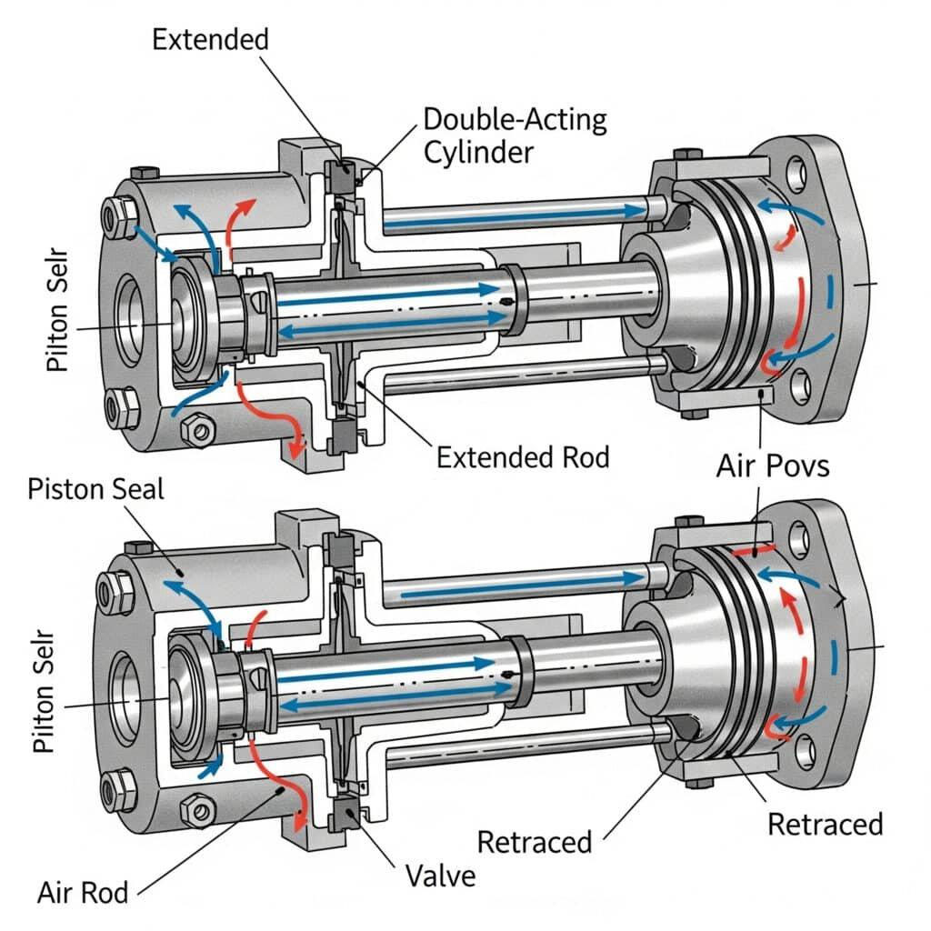
The basic working principle of a pneumatic cylinder is the relationship between air pressure, effective piston area, and force.
When compressed air enters one side of the piston, the pressure acts over the effective piston area. If the forces acting on the two sides are unbalanced, the piston experiences a net force and moves toward the lower-pressure side, provided that the net force is sufficient to overcome friction and the external load.
The piston rod then transfers this movement to the machine.
The theoretical force of a pneumatic cylinder can be calculated using:
F = P × A
Where:
For a typical single piston rod cylinder, the effective area is different during extension and retraction. The extension side uses the full piston area, while the rod side area is reduced by the cross sectional area of the piston rod.
Assume a pneumatic cylinder has a 40 mm bore and operates at 0.6 MPa gauge pressure. We want to calculate its theoretical extension force.
Step 1: Calculate the piston area.
The piston area is:
A = π × D² ÷ 4
Using a bore diameter of 40 mm:
A = π × 40² ÷ 4 ≈ 1,257 mm²
Step 2: Calculate the theoretical force.
When pressure is expressed in MPa and area in mm², their product gives force in newtons:
F = 0.6 × 1,257 ≈ 754 N
The cylinder therefore has a theoretical extension force of approximately 754 N, equivalent to roughly 77 kgf as a force unit conversion.
This does not mean the cylinder can safely lift a 77 kg load in every application. Actual available force is lower because of seal friction, pressure losses, mechanical resistance, and the force needed to accelerate the load. Lifting applications also require suitable load-holding and safety measures.
The example illustrates an important selection principle: increasing the bore generally increases theoretical force at the same pressure, but it also increases compressed-air consumption.
For equipment designers, the objective is to select a cylinder that provides sufficient force without unnecessary air consumption, excessive impact, or avoidable operating costs.
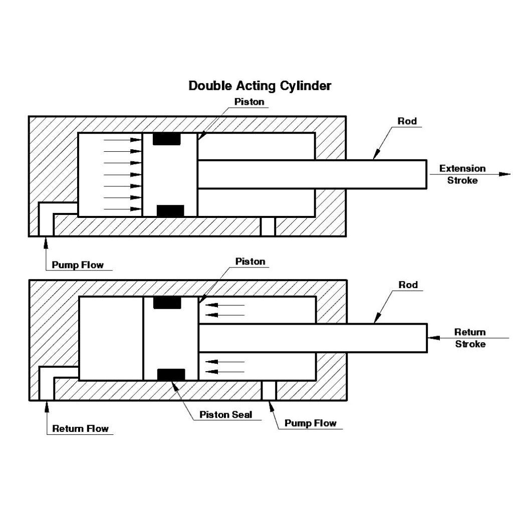
A double acting pneumatic cylinder uses compressed air to power both its extension and retraction strokes. It is widely used in industrial automation because the machine can actively control movement in both directions.
The operating process involves two main steps.
When the directional control valve directs compressed air into the cap-end chamber, the air pressure acts on the piston. The resulting net force moves the piston and extends the piston rod.
At the same time, air in the rod end chamber flows out through the valve's exhaust path.
The extended piston rod can then push a product, clamp a workpiece, or move a mechanical component into position.
After the extension stroke is complete, the directional control valve changes the airflow path.
Compressed air enters the rod end chamber and pushes the piston in the opposite direction. The piston rod retracts, while air in the cap end chamber exits through the exhaust path.
The cylinder is now ready for the next operating cycle.
In a typical single piston rod cylinder, the extension force is greater than the retraction force at the same pressure.
During extension, air pressure acts over the full piston area. During retraction, the piston rod occupies part of the piston area, leaving a smaller effective area for pressure to act on.
For example, consider a cylinder with a 40 mm bore, a 16 mm piston rod, and an operating pressure of 0.6 MPa.
Its theoretical extension force is approximately 754 N. Its theoretical retraction force is:
Retraction area = π × (40² − 16²) ÷ 4
Retraction area ≈ 1,056 mm²
Retraction force = 0.6 × 1,056 ≈ 633 N
The theoretical retraction force is therefore approximately 633 N, compared with 754 N during extension.
Actual forces will vary with friction, back pressure, operating conditions, and the cylinder design.
How is a single acting cylinder different?
A single acting cylinder uses compressed air for one working stroke and typically uses a spring or an external force for the return stroke.
It can be suitable for simpler mechanisms where powered movement in both directions is unnecessary. The appropriate type depends on the required motion, available space, load, and control requirements.
A pneumatic cylinder does not normally decide when to extend or retract. Its movement is controlled by the pneumatic circuit, particularly the directional control valve.
In an automated machine, the PLC provides the control logic, the solenoid valve directs the compressed air, and the cylinder converts the air pressure into mechanical movement.
Consider a simple pick-and-place or packaging machine.
First, the PLC sends an electrical signal to the solenoid valve. The valve changes its internal flow path and directs compressed air into one side of the cylinder. The piston moves, and the piston rod extends to push a component into position.
When the control system sends the next command, the valve changes the airflow direction. Compressed air enters the opposite chamber, and the piston rod retracts. The machine can then begin the next cycle.
A double-acting cylinder commonly uses a 5/2-way solenoid valve. The term means that the valve has five ports and two switching positions. In a typical arrangement, the valve supplies one cylinder chamber while connecting the other chamber to exhaust, then reverses those connections when it switches.
A single-acting cylinder commonly uses a 3/2-way valve, depending on the circuit design.
Sensors may also be installed to detect the cylinder's position. These signals allow the PLC to confirm that a movement has reached a defined point before starting the next operation.
However, a cylinder may still move too slowly even when the supply pressure appears correct. An undersized valve, restrictive tubing, excessive exhaust resistance, or a clogged muffler can limit airflow.
Reliable operation therefore depends on the complete pneumatic system, not just the cylinder or the solenoid valve alone.
A pneumatic cylinder's actual performance depends on several operating conditions. Understanding these factors helps equipment designers select suitable components and diagnose common problems.
Operating pressure
Higher pressure generally increases theoretical force, provided that the cylinder and associated components are rated for the operating conditions. Low or unstable pressure can cause insufficient force or inconsistent movement.
Bore size and piston rod diameter
The bore determines the piston area and strongly influences theoretical force. The rod diameter affects retraction force and contributes to mechanical stiffness.
Airflow and valve capacity
Pressure determines the potential force, but sufficient airflow is needed to fill the chamber at the required speed. A valve or tube that is too restrictive can slow cylinder movement.
Stroke length and load
A longer stroke may require additional attention to rod buckling, mounting stability, alignment, and overall mechanical rigidity. The load and required cycle time must also be considered.
Compressed-air quality
Water, particles, and unsuitable oil contamination can affect pneumatic components. ISO 8573-1:2010 classifies compressed-air purity according to contaminants including particles, water, and oil. The required purity class depends on the application and the component manufacturer's specifications.
Cushioning and alignment
Excessive impact at the end of the stroke can damage mechanical components. Poor alignment or excessive side loading can increase wear on the rod bearing and seals.
Common problems and what to check
| Symptom | Possible causes | Recommended checks |
| Insufficient force | Low pressure, excessive load, friction | Check operating pressure, load, and mechanical resistance |
| Slow movement | Restricted airflow, undersized valve, exhaust resistance | Check valve capacity, tubing, flow controls, and muffler |
| Inconsistent movement | Unstable air supply, leakage, changing load | Check supply stability, seals, and mechanical conditions |
| Excessive end impact | Incorrect cushioning, excessive speed, excessive load | Check cushioning, operating speed, and load |
These are general troubleshooting guidelines rather than definitive diagnoses. The actual cause should be confirmed by inspecting and testing the equipment.
Increasing the supply pressure is not always the best solution. In some cases, checking the valve capacity, tubing arrangement, exhaust path, and mechanical alignment can reveal the real cause of a performance problem.
Pneumatic cylinders are widely used in industrial automation because they can produce repetitive linear movement with relatively simple control systems.
Their basic working principle remains the same across applications: compressed air creates force, the piston moves, and the piston rod transfers the motion to a machine component. What changes is the mechanical task.
Packaging machinery
Cylinders operate pushers, product stops, sorting gates, and certain sealing mechanisms. They help move products into the correct position during repetitive packaging cycles.
Industrial assembly lines
Cylinders clamp workpieces, position components, and move parts between processing stations. They are often integrated with sensors and PLC-controlled sequences.
3C electronics manufacturing
Compact pneumatic cylinders can position small components and operate fixtures in equipment used to manufacture mobile phones, computers, and other electronic products. The required cylinder size and motion must match the precision and space constraints of the machine.
Automotive manufacturing
Pneumatic cylinders are used in workholding fixtures, material handling, part positioning, and other automated operations. The cylinder must be selected according to the load, stroke, cycle rate, and installation conditions.
Robotics and material handling
Pneumatic actuators can operate grippers, stops, and auxiliary mechanisms. Guided cylinders may be appropriate when an application requires additional resistance to side loads.
The key engineering decision is not simply whether a cylinder can move a component. It is whether the selected cylinder can perform the required movement reliably, repeatedly, and safely under the actual operating conditions.
Selecting a pneumatic cylinder begins with understanding the movement and load required by the machine.
Before choosing a cylinder, consider the following factors.
1. Required force
Determine the force needed in both directions. Calculate theoretical force and account for friction, external loads, acceleration, and pressure variation. Do not use theoretical force alone as the allowable working load.
2. Stroke length
Choose a stroke that provides the required travel without unnecessary movement. Long-stroke applications may require additional checks for rod stability and mounting rigidity.
3. Operating speed and cycle frequency
Determine how quickly the cylinder must complete each stroke and how frequently it will operate. Confirm that the valve, tubing, and air supply can provide sufficient airflow.
4. Mounting and load conditions
Check the installation space, alignment, and direction of the applied load. If a moving platform is subject to significant side forces, a guided actuator or an external guide system may be more suitable than relying on the piston rod alone.
5. Operating environment
Consider temperature, moisture, dust, cleanliness requirements, and the specifications of the selected components.
Routine maintenance should include checking for air leakage, loose mountings, damaged piston rods, unusual noise, inconsistent speed, and visible wear. Filters, regulators, and exhaust components should be inspected according to the equipment manufacturer's recommendations.
Maintenance and troubleshooting should be performed using appropriate isolation procedures. Compressed air must be safely isolated and stored energy released before servicing the pneumatic system.
For machine builders selecting MAXAIR pneumatic components, matching the cylinder with a correctly sized solenoid valve, suitable tubing, and properly prepared compressed air can help create a dependable pneumatic system. Final selection should always be based on the specific load, operating conditions, and verified product specifications.
pneumatic cylinder works by converting compressed-air pressure into linear mechanical motion. Air pressure acts on the piston, creating a net force that moves the piston and piston rod. In a double-acting cylinder, a directional control valve switches the airflow to make the rod extend and retract.
Although the principle is straightforward, reliable operation depends on selecting the correct bore and stroke, providing sufficient airflow, maintaining suitable air quality, and ensuring proper installation and load alignment.
For engineers, machine builders, and beginners learning industrial automation, understanding the relationship between compressed air, piston force, valve control, and mechanical load is the foundation of effective pneumatic system design. By considering the complete system rather than the cylinder alone, it becomes easier to select suitable components, identify performance problems, and build more reliable automated equipment.